Круглий стіл з нагоди настання Нового 2019 року
No Comments
Зробив собі ямбічний ключ.
Тисни далі по подробиці
Вирішив спробувати побудувати вертикал у дії. Сьогодні будуємо трансформатор для вертикала.

Тисни далі по подробиці.
Привіт всім сьогодні публікую статтю про то як створити просту антену з недорогих матеріалів.
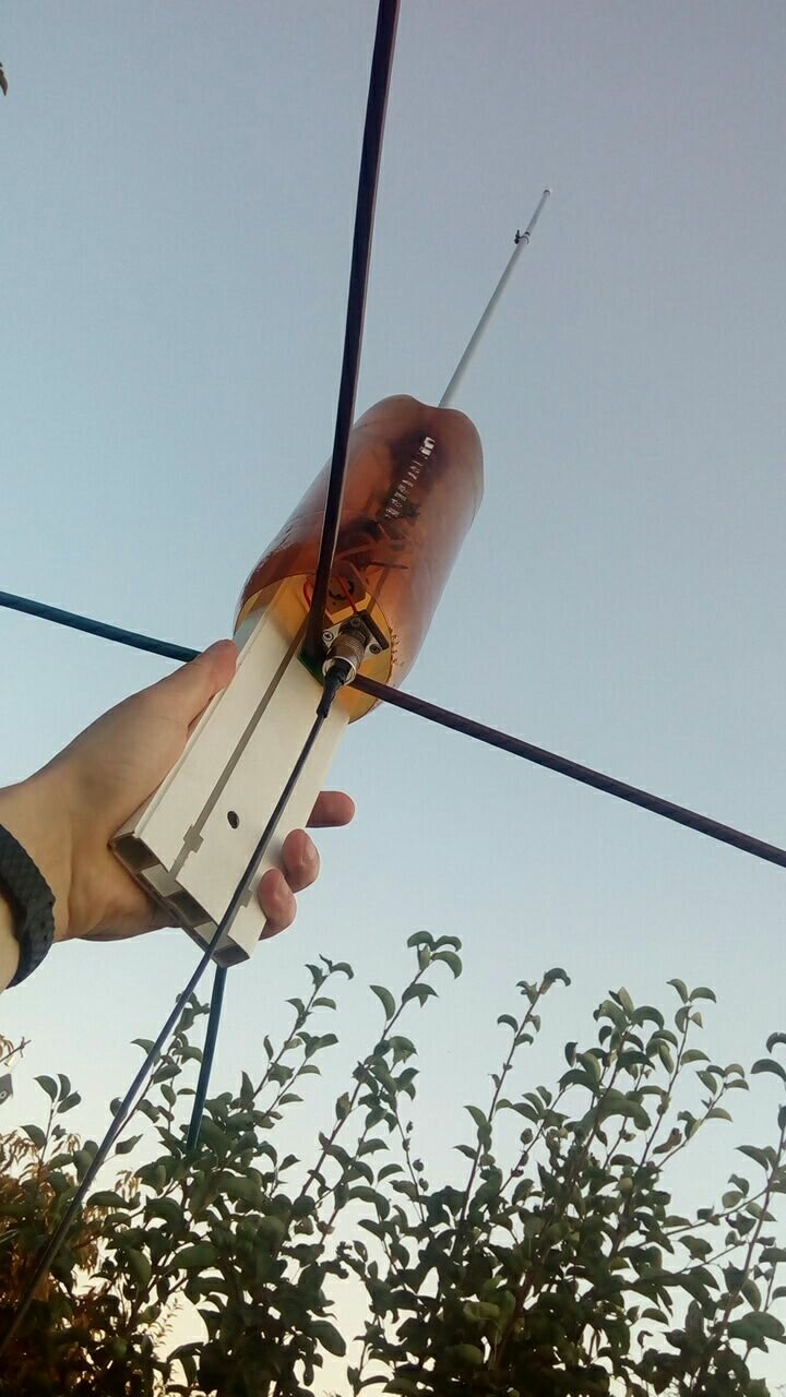
Тисни далі по подробиці.